

RELIABLE PUMP PERFORMANCE STARTS WITH CORRECT INSTALLATION
A centrifugal pump is a precision rotating machine, and the conditions created at installation stay with it for the whole of its working life. A rigid foundation and a properly leveled, grouted baseplate hold the pump and driver in position; correct alignment keeps loads off the coupling, bearings and seals; and correctly arranged piping protects both the suction conditions and that alignment.
Where any of these are compromised — a flexible foundation, an unlevel baseplate, pipe strain forced through the flanges, or an airtight suction line that is not actually airtight — the result is vibration, seal and bearing wear and loss of performance. Attention at installation is the least expensive way to protect long-term pump reliability. Matching the pump to the duty in the first place is covered under industrial pump selection .
INSTALLATION FACTORS THAT GOVERN PUMP LIFE
KEY STAGES OF INDUSTRIAL PUMP INSTALLATION
Protect the pump and machined surfaces until installation.
Rigid, vibration-absorbing support with correctly placed bolts.
Grout the baseplate after preliminary alignment.
Level the baseplate with shims and a spirit level.
Lift and move the unit safely, without strain on parts.
Check angular and parallel alignment of pump and driver.
Suction and delivery lines aligned naturally and supported.
Sealing liquid, cooling water and vacuum equalizing lines.
PUMP STORAGE BEFORE INSTALLATION
Where a pump is not installed immediately on arrival, it should be kept in a clean, dry, covered place, free from vibration, and protected from dust, moisture and mechanical damage until it is required.
- Store the pump under cover in a dry location, protected from dust and moisture.
- Leave the suction and delivery flange covers in place so that no foreign matter enters the pump.
- Keep machined and unpainted surfaces coated with a suitable rust preventive.
- Rotate the shaft by hand periodically during storage so that the rotating element does not settle in one position.
- Inspect the pump and its accessories for transit or storage damage before installation begins.
FOUNDATION PREPARATION FOR PUMP INSTALLATION
The foundation must be substantial enough to absorb vibration and to form a permanent, rigid support for the baseplate. A concrete foundation on a solid base is normally used. Its strength and mass are what keep the pump set in position once alignment has been established, so the foundation is prepared before the unit is set in place.
Foundation bolts of the correct size are set in the foundation in the positions shown on the general arrangement drawing for the pump. Each bolt is surrounded by a pipe sleeve of larger diameter than the bolt, so that the bolt can be moved within the sleeve to suit the final position of the baseplate holes. The baseplate is then lowered over the bolts and brought to its final position before leveling and grouting.
Rigid Support
The foundation carries the pump set and holds it permanently in position.
Vibration Absorption
Sufficient mass and strength to absorb vibration and strain in service.
Bolts and Sleeves
Anchor bolts set as per drawing, in sleeves that allow final adjustment.
PUMP BASEPLATE GROUTING
BEFORE GROUTING
- Set the baseplate in position over the foundation bolts and level it using shims or wedges.
- Carry out a preliminary alignment of the pump and motor before the grout is placed.
- Tighten the foundation bolts evenly and uniformly, taking care not to distort the baseplate.
GROUTING AND AFTER
- Fill the space beneath the baseplate completely with grout so that the baseplate is fully supported.
- Allow the grout to harden before any further tightening or alignment work is carried out.
- After the grout has hardened, tighten the foundation bolts finally and check the alignment again.
- Recheck alignment once more after the suction and delivery piping has been connected.
PUMP AND BASEPLATE LEVELING
With the baseplate resting on the foundation bolts, check the level of the baseplate with a spirit level, using shims or wedges under the baseplate to bring it true. Check the level both along and across the baseplate, and also on the machined pads carrying the pump and driver feet, so that neither machine is mounted on a twisted base.
- Use a spirit level on the machined surfaces of the baseplate.
- Adjust with shims or wedges close to the foundation bolts.
- Check level lengthwise and crosswise before grouting.
- Recheck the level after the foundation bolts are finally tightened.
SAFE PUMP HANDLING
The pump set should be lifted and moved carefully, with the slings arranged so that no load is taken by parts that are not intended to carry it. Handling damage before the unit reaches the foundation is a common and avoidable cause of installation problems.
- Lift a complete pump set by the baseplate, not by the pump or the motor alone.
- Do not take the lifting load on the shaft, coupling, bearing housing or piping connections.
- Keep the unit level while it is being lifted and lowered into position.
- Protect machined faces and flange facings from knocks during handling.
PUMP AND MOTOR ALIGNMENT
Correct pump and driver alignment is essential for reliable operation. Alignment should be checked again after leveling, grouting, foundation bolt tightening and connection of the suction and delivery piping.
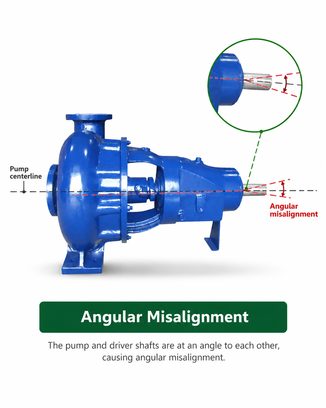
ANGULAR MISALIGNMENT
Angular misalignment is present when the two shafts are not in the same straight line but meet at an angle, so that the coupling faces are not parallel to each other. It is checked by measuring the distance between the coupling faces with a feeler gauge or taper gauge at four points around the coupling. The unit is in angular alignment when the measurement is the same at every point.
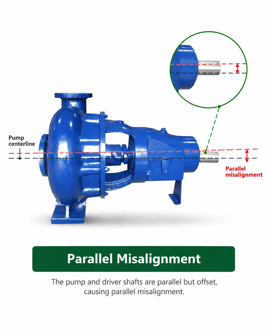
PARALLEL MISALIGNMENT
Parallel misalignment is present when the two shaft centre lines are parallel to each other but are offset, so that one coupling half stands higher than, or to one side of, the other. It is checked by laying a straight edge across the coupling rims at the top, bottom and both sides. The unit is in parallel alignment when the straight edge rests evenly on both coupling halves at every position.
INDUSTRIAL PUMP PIPING INSTALLATION
Correct piping arrangement is essential to protect pump alignment and support reliable hydraulic performance.
SUCTION & FEED LINE
Short, direct and airtight, laid with a continuous slope and free of air pockets.
DELIVERY LINE
Fitted with the required valves and arranged so that no load reaches the pump.
PIPE SUPPORT
Both lines carried on their own supports close to the pump connections.
PIPE STRAIN
Pipework aligned naturally to the flanges so that no strain reaches the casing.
Piping should align naturally with the pump connections. Do not force the piping into position using flange bolts.
Suction and delivery piping must be supported independently, and as near to the pump as possible, so that the weight of the pipework and any pipe strain is carried by the supports and not transferred to the pump. Strain transmitted through the flanges distorts the casing and destroys the alignment established during installation.
SUCTION PIPING REQUIREMENTS
The suction line should be as short and as direct as possible. Where the pump operates under suction lift, the line must be absolutely airtight — a leak that admits air will prevent the pump from priming and holding its prime, even though no liquid escapes.
- Lay the suction line with a continuous rise towards the pump, so that no high point can trap air. Where a feed (flooded suction) arrangement is used, lay the line with a continuous fall towards the pump.
- Avoid air pockets in the line; where a high point is unavoidable, provide a vent so that trapped air can be released.
- Where a reduction in pipe size is required at the pump suction, use an eccentric reducer fitted with the flat side uppermost, so that air cannot collect in the reducer.
- Where a foot valve is used, size it so that it does not add unnecessary resistance, and keep it submerged sufficiently to prevent air being drawn in through vortex formation.
- Fit a suction strainer of adequate free area to keep foreign matter out of the pump, and keep it clean in service.
- An isolating valve may be fitted in the suction line for maintenance, but it must be fully open when the pump is running; do not use it to throttle the pump.
- Line short, direct and airtight
- Continuous slope, no air pockets
- Vent provided at any unavoidable high point
- Eccentric reducer with flat side up
- Foot valve and strainer correctly sized
- Isolating valve fully open in operation
DELIVERY PIPING ARRANGEMENT
VALVES
- A non-return (reflux) valve is fitted in the delivery line to protect the pump against reverse flow and against shock when the pump is stopped.
- A delivery isolating valve is fitted beyond the non-return valve, for starting, regulation and isolation during maintenance.
ARRANGEMENT
- Keep the delivery line as direct as practicable and avoid unnecessary bends and fittings that add friction loss.
- Where the pipe size is increased at the pump discharge, use a gradual taper piece so that the change of section is smooth.
SUPPORT
- Support the delivery line independently, close to the pump, so that its weight is not carried by the pump branch.
- Bring the pipework to the flange without force; the flange faces must meet naturally, square and true.
SEALING, COOLING & VACUUM CONNECTIONS
SEALING LIQUID LINES
Where the stuffing box or mechanical seal requires a sealing liquid, connect the sealing liquid line to the tapping provided on the pump. The sealing liquid must be clean and available at the required pressure whenever the pump is running, so that the seal faces or packing are lubricated and the gland is kept free of air and abrasive matter.
COOLING WATER LINES
Where cooling is specified for the stuffing box, seal or bearing housing, connect the cooling water lines to the connections provided. A clean and uninterrupted supply of cooling water must be available while the pump is in operation, and the flow should be checked at commissioning.
VACUUM EQUALIZING PIPE
Where the arrangement calls for a vacuum equalizing pipe, connect it as shown on the pump arrangement drawing so that the pressure at the point concerned is balanced. The line must be free of leaks and kept clear so that the intended balancing effect is maintained.
INDUSTRIAL PUMP INSTALLATION CHECKLIST
A practical summary of the installation guidance on this page. It is a summary only, and does not replace the instruction manual and arrangement drawings supplied with the specific pump.
BEFORE INSTALLATION
- Inspect pump and accessories
- Check for shipping/storage issues
- Confirm installation requirements
FOUNDATION & BASEPLATE
- Foundation prepared
- Anchor bolts positioned
- Baseplate positioned
- Level checked
- Grouting completed
ALIGNMENT
- Pump and driver alignment checked
- Angular alignment checked
- Parallel alignment checked
- Alignment rechecked after piping
PIPING
- Suction line checked
- Delivery line checked
- Pipe supports provided
- Pipe strain avoided
CONNECTIONS
- Sealing liquid connections checked
- Cooling water connections checked
- Vacuum equalizing arrangement checked where applicable
IMPORTANT
This page provides general installation guidance. Always follow the installation, operation and maintenance instructions supplied for the specific SAM Turbo pump model, approved arrangement drawings and applicable site safety procedures. Installation and alignment work should be performed by appropriately trained and qualified personnel.
FROM INSTALLATION TO COMMISSIONING
Correct installation is the foundation for reliable pump operation. Once installation, alignment and piping work are complete, the pump should proceed through the appropriate commissioning checks before entering service.
NEED SUPPORT WITH YOUR PUMP INSTALLATION?
Installation requirements can vary with pump configuration, application and site conditions. Connect with SAM Turbo's engineering team for technical guidance related to your pumping system.


