

INDUSTRIAL PUMP TROUBLESHOOTING: START WITH THE SYMPTOM, THEN INVESTIGATE THE CAUSE
Pump troubleshooting begins with identifying the observed symptom and checking the operating conditions systematically. A single pump symptom can have multiple causes, so hydraulic conditions, mechanical condition and system operation should be reviewed before corrective action is taken.
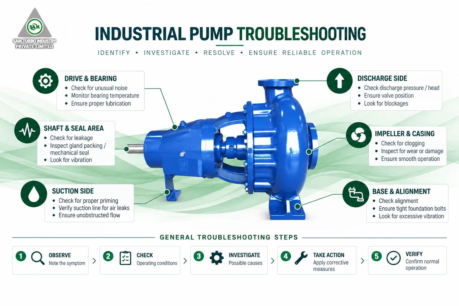
The troubleshooting process should move from the symptom to measurable operating conditions, then to hydraulic, mechanical and component-related causes before corrective action is taken.
WHAT PUMP SYMPTOM
ARE YOU EXPERIENCING?
PRESSURE/HEAD
CONSUMPTION
LEAKAGE
SYMPTOM → POSSIBLE
CAUSE → CHECK /
ACTION
Use this chart to guide initial checks. A symptom may have several interacting causes; isolate conditions methodically and follow site safety procedures and the pump instruction manual.
| SYMPTOM | POSSIBLE CAUSE | CHECK / ACTION |
|---|---|---|
|
01
No liquid delivery
|
Pump not primed; suction path obstructed or leaking; insufficient liquid level; incorrect rotation; closed valve. | Confirm casing and suction line are filled. Check suction valves, strainers, liquid level, air ingress and direction of rotation. |
|
02
Insufficient flow
|
Excessive system resistance; restricted suction; speed or rotation issue; worn hydraulic parts; operation away from duty point. | Compare measured flow and head with the duty point. Inspect valve positions, strainers, pipework, speed and internal clearances. |
|
03
Insufficient pressure/head
|
Air or gas in liquid; incorrect speed; worn impeller; low system resistance causing excess flow; incorrect impeller condition. | Verify pressure instruments, speed and operating point. Vent trapped air and inspect impeller and wear components if external checks are satisfactory. |
|
04
Excessive power consumption
|
Flow too high; liquid properties differ from design; mechanical contact; misalignment; tight packing or bearing condition. | Measure current and flow. Check fluid density/viscosity, valve setting, alignment, shaft freedom, packing adjustment and bearings. |
|
05
Excessive vibration
|
Cavitation; misalignment; pipe strain; loose foundation; imbalance; worn bearings; operation away from preferred range. | Record vibration by location. Check suction margin, alignment, pipe support, hold-down bolts, coupling, bearings and rotating parts. |
|
06
Abnormal noise
|
Cavitation or air entrainment; bearing distress; component contact; loose parts; foreign material. | Identify where and when noise occurs. Review suction conditions, venting and lubrication, then inspect clearances and fasteners. |
|
07
High bearing temperature
|
Incorrect lubricant quantity or grade; contamination; misalignment; excessive load; cooling restriction; bearing damage. | Trend temperature. Confirm lubrication per the operation/instruction manual, alignment and cooling flow. Do not allow bearing temperature to exceed 80°C. |
|
08
Excessive seal/packing leakage
|
Seal faces or packing worn; shaft movement; incorrect adjustment; inadequate flush/cooling; unsuitable sealing arrangement. | Check leakage pattern, seal support, flush and cooling. Inspect shaft runout and sleeve condition; adjust packing only as instructed. |
|
09
Pump loses prime
|
Air leak in suction line; liquid level too low; foot/check valve issue; gas release; vortexing or inadequate submergence. | Leak-test the suction path. Verify liquid level, submergence, valve function, venting and stable suction conditions. |
|
10
Unstable operation
|
Variable supply; intermittent air entry; operation near shut-off or run-out; control-valve hunting; two-phase flow. | Trend flow, pressure and current together. Stabilize inlet conditions and controls, then compare the operating point with the pump curve. |
CHECK THE
SYSTEM BEFORE
BLAMING THE
PUMP
Confirm actual flow, head and suction pressure against the selected operating point. Review liquid level, available NPSH, cavitation indicators, system resistance, valve configuration, pipe restrictions and fluid properties such as density, viscosity, temperature and entrained gas.
CHECK ALIGNMENT,
BEARINGS AND ROTATING
COMPONENTS
CHECK THE
COMPONENTS THAT
CONTROL RELIABILITY
Inspect mechanical seals, packing, sleeves and flush arrangements. Leakage, heat or deposits can indicate wear, shaft movement, poor adjustment or unsuitable support conditions.
Use the specified lubricant and refer lubricant quantity and interval to the pump operation/instruction manual. Check for contamination, foaming, leakage or overfilling.
Confirm cooling-water flow and unobstructed passages. Bearing temperature should not exceed 80°C; cooling-water temperature rise should not exceed 15°C.
A STRUCTURED PATH
FROM SYMPTOM TO
SOLUTION
CHANGES IN CONDITION
ARE EARLY WARNING
SIGNS
Routine readings establish the baseline. A change in pressure, flow, vibration, noise, temperature, leakage or power demand should trigger investigation before reliability is compromised.
SUPPORT THROUGH THE
PUMP LIFECYCLE
CONTINUE WITH SAM
TURBO ENGINEERING
GUIDANCE
INDUSTRIAL PUMP
TROUBLESHOOTING
QUESTIONS
ANSWERED
NEED HELP
IDENTIFYING A PUMP
PROBLEM?
Share the symptom, operating conditions and available measurements with our engineering team for a focused technical discussion.


