

INTRODUCTION
Multistage Pumps are centrifugal pumps designed to deliver high pressure and head in applications where a single-stage pump may not meet the required operating conditions. They use multiple impellers arranged in series on a common shaft, allowing each stage to add energy to the liquid and progressively increase its pressure. The liquid passes through successive impellers and diffusers, building the total head required for the application. Multistage centrifugal pumps are commonly used in boiler feed systems, industrial water supply, power generation, mining, water treatment and high-pressure process applications. Their performance depends on factors such as flow rate, total head, liquid properties, operating temperature and system requirements. Understanding how these pumps generate pressure helps engineers select suitable equipment for reliable and efficient industrial operation.
SAM Turbo Industry Pvt. Ltd manufactures Multistage Pumps (MD/MDP) for industrial pumping requirements. With over 55 years of experience in pump manufacturing, SAM Turbo combines application-specific engineering with material selection, in-house manufacturing, machining and pump testing to address diverse industrial needs. Choosing an appropriate multistage pump involves evaluating the required flow, discharge pressure, operating conditions and characteristics of the liquid being handled. By considering these application requirements during pump selection, engineers can identify a suitable pumping solution for their plant operations. Explore SAM Turbo’s MD/MDP multistage pump range to learn more about its product offering and industrial applications.
What Is a Multistage Centrifugal Pump?
A Multistage Centrifugal Pump is a centrifugal pump with two or more impellers mounted on a common shaft inside one casing. Liquid enters at the suction, is accelerated by the first impeller, guided by a diffuser or return channel to the eye of the second impeller, and so on, until it leaves the last stage at discharge pressure. Each stage is essentially a small single-stage pump feeding the next one.
The reason for this arrangement is practical. Head developed by a single impeller depends on its tip speed, so achieving very high head with one impeller needs a very large diameter or very high speed, both of which bring mechanical, efficiency and cost penalties. Splitting the duty across stages keeps every impeller at a moderate, efficient size.
How Pressure Builds Stage by Stage
The staircase below shows the principle. Each stage adds a similar increment of head, so discharge pressure climbs step by step while flow remains constant through the pump.
0%
17%
33%
50%
67%
83%
100%
Suction
Stage 1
Stage 2
Stage 3
Stage 4
Stage 5
Stage 6 / Discharge
Stage-by-stage pressure build-up in a multistage pump — illustrative, six equal stages shown as share of total discharge head.
Following the Liquid Through the Pump
It helps to follow a single volume of liquid from suction to discharge. The path below repeats for every stage, which is why the pump can be understood one stage at a time.
Suction
Liquid enters at suction pressure and is guided to the first impeller eye.
Impeller
Rotating vanes accelerate the liquid outward, adding velocity and some pressure.
Diffuser / return channel
Velocity is slowed and converted into pressure; flow is redirected inward.
Next stage
The liquid enters the next impeller eye at a higher pressure than before.
Repeat
Impeller and diffuser steps repeat in every remaining stage.
Discharge
The last stage delivers the liquid at total developed pressure.
Flow path through a multistage centrifugal pump, stage by stage.
The Working Principle: Impeller, Diffuser and Energy Transfer
Energy moves through a multistage pump in two repeated steps. First, the rotating impeller imparts kinetic energy to the liquid by throwing it outward through the vanes, raising its velocity. Second, the stationary diffuser or return channel slows that high-velocity liquid down, converting much of the velocity into pressure and redirecting the flow to the next impeller eye. This pair of steps repeats in every stage.
| Component | Function | Energy Effect |
|---|---|---|
| Suction / inlet | Brings liquid smoothly to the first impeller eye | Sets the suction pressure available |
| Impeller | Rotates on the shaft and accelerates liquid outward | Adds kinetic energy and some pressure |
| Diffuser / return channel | Slows the liquid and guides it to the next impeller | Converts velocity into pressure |
| Crossover passage | Directs liquid between stages (or to discharge) | Carries pressurised liquid with minimal loss |
| Shaft and bearings | Carry all impellers and the rotating load | Transmit power from the driver |
| Discharge | Collects liquid from the final stage | Delivers total developed pressure |
Key relationship: Total head of a multistage pump ≈ head per stage × number of stages, while the flow rate through each stage is the same. Power rises with both flow and total head, using P = ρ × g × Q × H / η.
Flow, Head and Pressure Across Stages
Because the stages work in series, the liquid passes through each one in turn. This leads to three simple rules that help when reading a multistage pump curve:
- Flow is the same at every stage; the liquid leaving one stage is exactly what enters the next.
- Head adds up stage by stage, so adding stages raises total head without changing the flow range.
- Pressure at discharge equals suction pressure plus the pressure produced by all stages combined.
Worked example (illustrative only): A duty needs 300 m of total head at 100 m³/h (0.0278 m³/s) of water. If each stage develops about 50 m, six stages are needed. Hydraulic power at 70% efficiency is P = 1000 × 9.81 × 0.0278 × 300 / 0.70 ≈ 117 kW. Final selection should always be confirmed against the manufacturer’s tested curves.
Where multistage pumps work together with other pumps, series and parallel arrangements change these rules; SAM Turbo’s guide to parallel vs series pump operation covers that comparison. For reading the curves themselves, see the pump curve and BEP guide.
Why Head Per Stage Is Limited
- The Head an Impeller can develop rises with the square of its tip speed. This is why a single impeller cannot simply be asked for more: doubling the head needs roughly 40% more tip speed, which means a larger diameter or higher rpm, and both bring higher mechanical stress, more vibration risk and, usually, lower efficiency away from the design point. A multistage pump avoids this by keeping every impeller within a comfortable range of size and speed and letting the stage count carry the head.
- Stage count also shapes the pump curve. Adding stages scales the head-flow curve upward by roughly the same factor at every flow, while the flow range and best efficiency flow stay governed by the impeller and diffuser design. That is why two pumps with the same impeller but different stage counts have similarly shaped curves at different heights.
Axial Thrust and Balancing in Multistage Pumps
- With several impellers on one shaft, the pressure difference across each impeller pushes the rotor in one direction, and these forces add across all stages. Left unbalanced, the resulting axial thrust would overload the thrust bearing. Multistage designs therefore include a balancing method — commonly a balance drum or disc that uses discharge pressure to counter the thrust, or impellers arranged in opposed groups so their thrusts cancel. The precision-balanced rotating assembly used in SAM Turbo’s Multistage Pumps (MD/MDP) reflects the importance of this part of the design.
- Renewable wear components matter here too. Wear rings and interstage bushes keep leakage between stages low, and as clearances open up with service, leakage rises and efficiency drops. Being able to renew these parts, rather than replace whole stages, is what keeps lifecycle cost down in high-pressure duty.
Practical Examples
- In boiler feed service, a multistage pump takes deaerated feed water at a modest suction pressure and delivers it above boiler drum pressure. The suction side is the critical design point because the water is hot, so NPSH margin and a steady, flooded supply are essential. In mine dewatering, the pump lifts water through a long vertical rise, and the stage count is chosen to provide the total head of the static lift plus pipe friction. Here the duty tends to be steady and continuous, which rewards a pump operating close to its best efficiency point. In a pressure-boosting or reverse-osmosis feed application, the key requirement is stable pressure at the membrane or distribution inlet, which suits the smooth, pulsation-free output of a centrifugal multistage design.
- In every case the same questions apply: what total head is needed, what flow, what suction conditions, and what fluid. Answering those four reliably is what turns the working principle into a correct selection.
Single-Stage vs Multistage Pumps
The easiest way to see why multistage designs exist is to compare how each approach reaches the same head.
Single-stage: one big step
One impeller must deliver the entire head: larger diameter or higher speed, higher mechanical stress.
Multistage: many small steps
Several moderate impellers share the head: compact, efficient and smoother to run.
Single-stage vs multistage pump — how each reaches the same total head.
| Factor | Single-Stage Pump | Multistage Pump |
|---|---|---|
| Head capability | Moderate | High — scales with number of stages |
| Impeller size for high head | Large diameter or high speed | Moderate diameter per stage |
| Footprint for high pressure | Larger or needs very high speed | Compact for the pressure delivered |
| Complexity and cost | Simpler, lower cost | More parts, higher cost and maintenance |
| Best suited to | High flow, low to moderate head | Moderate flow, high head and pressure |
Major Types of Multistage Pumps
| Type | Description | Typical Use |
|---|---|---|
| Barrel-type (double casing) | Inner stage assembly inside an outer pressure-containing barrel | High pressure and temperature duties such as boiler feed |
| Segmental / ring-section | Stages built from stacked ring sections held by tie bolts | General high-pressure water service and boosting |
| Horizontal multistage | Shaft horizontal, stages in line along the shaft | Industrial process and plant water services |
| Vertical multistage | Shaft vertical, often compact in footprint | Pressure boosting, space-limited installations |
| Two-stage split case | Two impellers in a horizontally split casing | Higher head than single-stage with easy inspection |
Industrial Applications
Where multistage pumps are used.
In boiler feed service, a multistage pump has to supply water at a pressure well above drum pressure. In mine dewatering, it lifts water through long vertical heights where a single impeller could not generate enough head. In pressure boosting and RO feed, it delivers the steady high pressure that membranes or distribution networks require. Each of these is a high-head, moderate-flow duty, which is exactly where stacking stages pays off.
Advantages and Limitations
Advantages
✓ High head and pressure from a single machine
✓ Moderate impeller size keeps efficiency good
✓ Compact for the pressure produced
✓ Smooth, continuous, pulsation-free flow
✓ Wide use of standard centrifugal technology
Limitations
● More parts, so more maintenance than single-stage
● Less suited to solids-laden or highly abrasive liquids
● Sensitive to operating far from the best efficiency point
● Needs adequate suction conditions and minimum flow protection
● Alignment and balance matter more on long shafts
Common Misconceptions
SAM Turbo Multistage Pumps (MD/MDP)
SAM Turbo’s Multistage Pumps (MD/MDP) are multi-stage centrifugal pumps with impellers arranged in series to build discharge pressure, in a robust barrel-type construction with a precision-balanced rotating assembly, renewable wear components and a heavy-duty shaft supported by precision bearings. Sealing is by gland packing or mechanical seal, selected to suit the operating conditions.
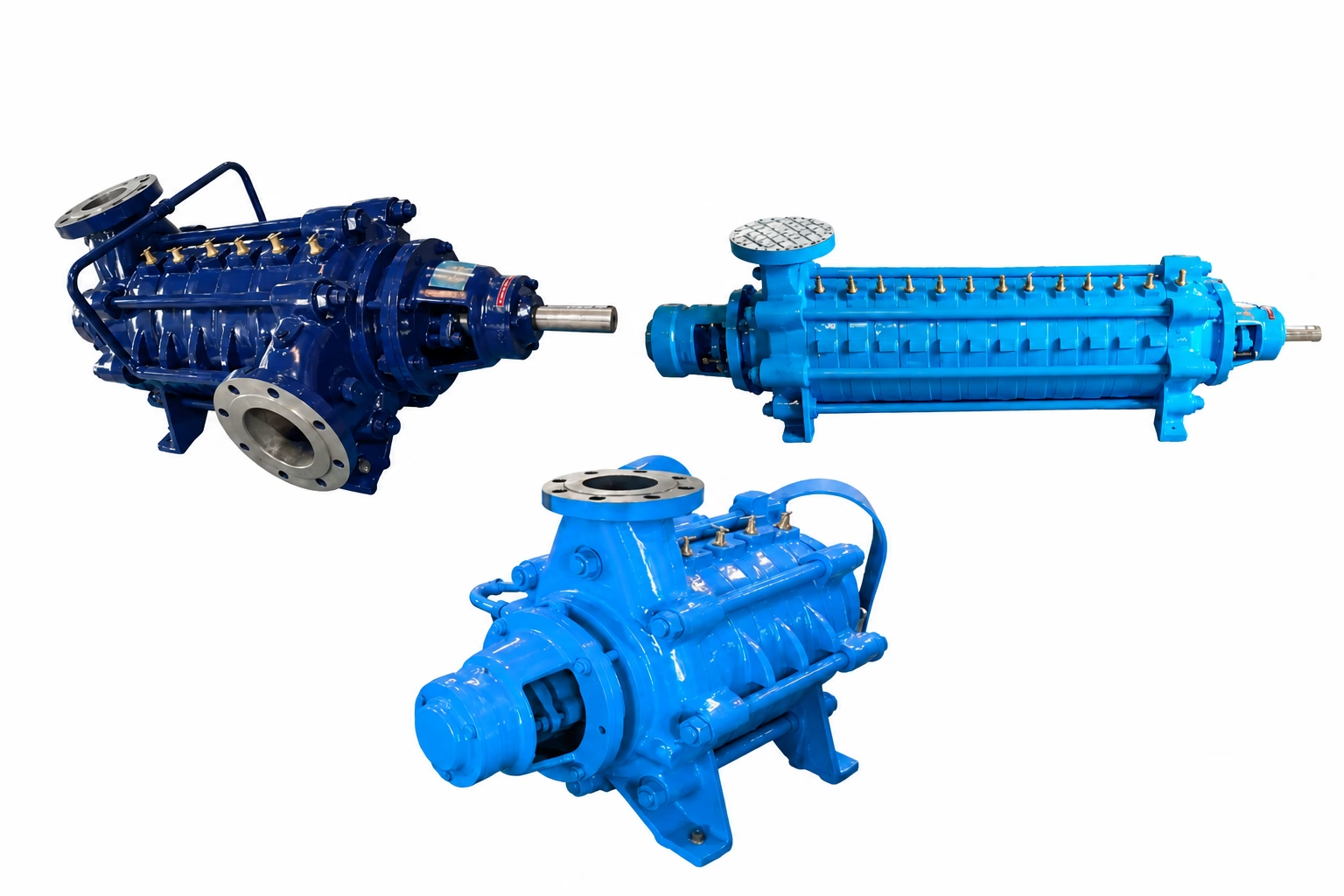
Delivery size: DN 40 to 125 mm
Capacity: Up to 350 m³/hr
Head: Up to 600 m
Maximum working pressure: Up to 90 bar
Temperature: Up to 120°C
Construction: Multi-stage centrifugal, barrel-type casing, renewable wear components
The range is intended for clean water, condensate, boiler feed water, industrial process water, cooling water and other non-abrasive, low-viscosity fluids, across boiler feed, condensate extraction, mine dewatering, fire fighting, pressure boosting, RO feed and power plant auxiliary services. SAM Turbo’s in-house manufacturing, material control, precision machining and performance testing sit behind each unit, and the engineering team reviews duty, fluid and suction conditions with customers at selection stage. For other duties, see the Horizontal Split Case Pumps, the Process Pumps (TCH+N) or the full industrial pump range.
Frequently Asked Questions
How does a multistage centrifugal pump generate high pressure?
It passes liquid through several impeller-and-diffuser stages in series. Each stage adds head, so the total developed pressure is the sum of all stages.
What is the function of the diffuser in a multistage pump?
The diffuser slows the fast-moving liquid leaving an impeller, converting velocity into pressure and guiding the liquid to the next impeller.
Does adding stages increase flow?
No. Stages add head, not flow. Flow is the same through every stage and is set by the impeller and casing hydraulics.
How is total head calculated?
Total head is approximately the head per stage multiplied by the number of stages, subject to confirmation against the manufacturer’s tested performance curve.
When should I choose a multistage pump over a single-stage pump?
When the duty needs high head or pressure at moderate flow, where a single impeller would need to be very large or run at very high speed.
What fluids suit multistage centrifugal pumps?
Clean, non-abrasive, low-viscosity liquids such as water, condensate, boiler feed water and process water. Abrasive or solids-laden liquids need other designs.
What are typical applications of multistage pumps?
Boiler feed, condensate extraction, mine dewatering, fire fighting, pressure boosting, RO feed, cooling water circulation and power plant auxiliaries.
What are the limitations of multistage pumps?
They have more parts and need more maintenance, are less suited to abrasive liquids, and need good suction conditions and operation near the best efficiency point.
What is the difference between barrel-type and segmental multistage pumps?
Barrel-type pumps house the stage assembly inside an outer pressure-containing barrel, suiting high pressure and temperature. Segmental pumps stack ring sections held by tie bolts.
What head and pressure do SAM Turbo Multistage Pumps (MD/MDP) cover?
The range covers heads up to 600 m and working pressures up to 90 bar, in delivery sizes DN 40 to 125 mm, with capacities up to 350 m³/hr and temperatures up to 120°C.
Conclusion
Multistage pumps generate high pressure by doing the same job repeatedly: each impeller adds kinetic energy, each diffuser turns it into pressure, and the stages together add up to the total head the system needs, while flow stays constant through every stage. That simple principle explains why multistage designs dominate boiler feed, dewatering, boosting and other high-head duties, and why they are the sensible alternative to a single oversized impeller.
SAM Turbo’s Multistage Pumps (MD/MDP) are built, machined and tested around these principles. If you are planning a high-pressure duty, SAM Turbo’s engineers can help match the pump to your fluid, pressure and suction conditions.
Planning a high-pressure pumping duty?
SAM Turbo’s engineering team can help you select the right multistage pump for your head, flow and fluid.


