

INTRODUCTION
Centrifugal Pump Internal Flow Instability can occur even when a pump is perfectly sized on paper, installed according to specifications and operating within its expected parameters. The pipework may appear steady and the pressure gauges may show acceptable readings, yet the liquid inside the pump casing may not be flowing smoothly. This hidden hydraulic disturbance causes backflow, vortices, flow separation and pressure pulsations, potentially leading to vibration, noise and premature impeller wear.
This guide explains why internal flow instability occurs, how centrifugal pump flow recirculation differs between the suction and discharge sides, and how flow separation and pressure pulsations affect vibration, bearings, hydraulic efficiency and overall pump reliability. It also explores practical ways for plant teams to identify and minimise these issues. Additionally, it highlights how SAM Turbo’s Horizontal Split Case Pumps (ZM/AD), Mixed Flow Pumps (MF) and Process Pumps (TCH+N) fit into reliable industrial pumping applications, supported by more than 55 years of application-focused pump manufacturing experience, a captive steel foundry, in-house machining and pump testing capabilities.
2
recirculation types
3
warning signs: vibration, noise, pulsation
BEP
the most stable flow point
Z × rpm ÷ 60
vane-pass frequency
Quick answer: Internal flow instability develops when a pump runs far from its best efficiency point (BEP) or when its suction, impeller or casing geometry forces the flow to separate. The result is recirculation, pressure pulsation, vibration, noise, higher bearing loads and lost efficiency. The fix starts with the operating point, then the suction conditions, then the hydraulic design.
What Is Internal Flow Instability in a Centrifugal Pump?
Inside a healthy pump, liquid enters the impeller eye, turns, and follows the vane channels outward with each blade guiding the flow. That only happens cleanly near the flow the impeller was designed for. At lower or higher flow the liquid meets the blade at the wrong angle (the incidence angle), the boundary layer detaches from the vane surface, and parts of the stream reverse direction. These disturbances are called internal because they occur inside the pump even while the pipeline flow looks steady.
Unlike cavitation, which is driven by low pressure and vapour bubbles, hydraulic instability is driven by flow angles and geometry. The two often appear together, which is why damage is sometimes misdiagnosed; SAM Turbo’s NPSH calculation guide covers the cavitation side, while this article concentrates on the flow behaviour that causes recirculation and pulsation.
Where Instability Starts: A Flow-Path Map
The simplified front view below marks the four places where most internal disturbances begin. Numbers match the cards underneath.
Discharge →
EYE
suction
Suction →
Simplified front view of an impeller and volute casing — schematic, not to scale.
1. Eye tip
Suction recirculation: backflow starts where the stream enters the eye at low flow.
2. Vane channel
Flow separation: the stream detaches from the vane surface at the wrong incidence angle.
3. Vane tip
Discharge recirculation: liquid slips back into the impeller at the outlet.
4. Cutwater
Pressure pulsation: each vane passing the tongue creates a pressure pulse.
Suction vs Discharge Recirculation
Recirculation is the best-known form of internal instability. It is not one phenomenon but two, starting at opposite ends of the impeller, and the cure for one does not always help the other.
Suction and discharge recirculation compared.
Both forms tend to appear once flow falls below a threshold that varies by design. As a general engineering guide, they can become noticeable somewhere between roughly 50% and 80% of BEP flow, with larger eyes and higher energy levels moving the threshold upward. The manufacturer’s data for the specific impeller, not a rule of thumb, sets the real limit, and SAM Turbo’s pump curve and BEP guide shows how to read it.
Flow Separation and Pressure Pulsations
When the stream detaches from a vane, the channel fills with slow, swirling liquid that blocks part of the passage. Flow separation can then become rotating stall, where one or more blocked channels travel around the impeller at a fraction of running speed, producing sub-synchronous vibration. In a volute pump the high-pressure jet leaving each vane also strikes the cutwater, creating a pulse each time a vane passes.
Vane-pass frequency (Hz) = number of vanes × speed (rpm) ÷ 60
Illustrative example: 6 vanes at 1,480 rpm → 6 × 1,480 ÷ 60 = 148 Hz
Near BEP this pulse is small. Away from BEP it grows, and the trace below shows the difference. Stable flow produces a regular, low waveform; unstable flow adds larger swings and irregular peaks that fatigue the casing, piping and bearings.
Near BEP: small, regular pulses
time →
Far from BEP: large, irregular pulses
time →
Illustrative pressure-pulsation traces — shape only, not measured data.
Engineer’s note: A spectrum with a dominant peak at vane-pass frequency points to a gap or flow-angle problem at the impeller outlet. Peaks well below running speed (roughly 0.2 to 0.8 times) point to rotating stall or recirculation. Our pump vibration analysis guide shows how to separate them.
What Influences Hydraulic Stability
Impeller and Casing Geometry
A larger eye improves suction performance but lets recirculation start at a higher flow. More vanes reduce slip and loading per blade but raise the pulse frequency; fewer vanes do the opposite. At the casing, a small radial gap between the impeller tips and the cutwater sharpens the pressure pulse, while a larger gap softens it at some cost to head and efficiency. The pump impeller types guide explains these trade-offs in more depth.
Flow Rate and Operating Point
Operating point is the biggest single driver. Running at 40% of BEP is not simply a “low flow” condition, it is a different hydraulic regime. Oversized pumps, heavily throttled valves and variable demand all push the duty point away from BEP, a pattern discussed in our article on the effect of oversizing pumps.
Suction Conditions and Piping
Uneven inflow produces uneven flow in the impeller. Short bends right before the suction nozzle, partly open valves and poor sump design all distort the velocity profile, and the distortion shows up as separation and noise. Double-suction pumps are sensitive to the orientation of an elbow just upstream, because it can feed the two eyes unequally.
The table summarises how common design and operating choices push stability in either direction.
| Factor | Change | Effect on stability | Practical note |
|---|---|---|---|
| Operating flow | Far below BEP | Recirculation and separation increase | Keep duty inside the preferred operating region |
| Impeller eye size | Larger | Suction recirculation begins at a higher flow | Balance against NPSH needs |
| Vane count | More vanes | Smoother loading, higher pulse frequency | Check resonance with piping |
| Cutwater gap | Smaller | Larger pulse amplitude | A bigger gap softens pulses with minor efficiency loss |
| Suction piping | Bend close to inlet | Uneven inflow, separation | Allow straight run; orient elbows correctly |
| Speed | Reduced (VFD) | Lower velocities and pulse energy | Check minimum speed and system curve |
| Liquid properties | Higher viscosity or gas content | Altered flow angles and head | Correct the curve or review selection |
Factors that influence internal hydraulic stability — general engineering guidance.
Effects on Vibration, Noise, Bearings, Efficiency and Reliability
The consequences are cumulative. Pulsation shakes the casing and pipework, uneven pressure around the impeller loads the shaft, and recirculating liquid wastes energy as heat. The chart compares an illustrative pump near BEP with the same pump far off BEP; each dot is an index where 1.0 means the near-BEP condition.
Vibration
3.2×
Pressure pulsation
3.8×
Radial bearing load
3.0×
Noise
2.2×
Seal and bearing wear rate
3.5×
Energy lost per unit flow
1.8×
Near BEP (1.0×)
Far from BEP
Near-BEP vs off-BEP impact index — illustrative, not test data.
- Vibration and noise: pulsation and stall excite the casing, base and piping, and broadband noise often sounds like gravel or crackling.
- Bearing loads: uneven pressure around the impeller raises radial force, deflecting the shaft and shortening bearing life.
- Seal life: shaft deflection and pressure swings hurt mechanical seal faces; see the mechanical seals guide.
- Efficiency: recirculation circulates energy that never becomes useful flow, and the wasted power appears as heat.
- Reliability: repeated fatigue cycles crack vanes, loosen fasteners and accelerate wear-ring wear.
Troubleshooting Internal Flow Instability
Start from the symptom, check the likely cause and confirm with measurement before changing hardware. The chart below turns that sequence into a quick reference; SAM Turbo’s troubles check chart covers wider pump faults.
If you see
Pump noisy at part load
→
Check
Compare duty point with the BEP on the curve
→
Likely cause
Suction recirculation or separation
If you see
Strong vane-pass peak in the spectrum
→
Check
Check cutwater gap, trim and flow
→
Likely cause
Discharge recirculation or tight gap
If you see
Sub-synchronous vibration
→
Check
Check flow against minimum stable flow
→
Likely cause
Rotating stall
If you see
Pitting at vane inlet
→
Check
Check NPSH margin and low-flow operation
→
Likely cause
Cavitation or suction recirculation
If you see
Vibration changed after piping work
→
Check
Inspect inlet elbow, valves and alignment
→
Likely cause
Distorted inflow or misalignment
Symptom-to-cause troubleshooting flow.
After the symptom check, a short sequence usually resolves the ambiguity:
- Record flow, head, power and vibration at several points across the operating range, not just at the normal duty.
- Compare the measured duty point with the manufacturer’s preferred and allowable operating region.
- Review the suction layout and any recent piping or valve changes.
- Check clearances, wear-ring condition and impeller trim.
- Confirm results with vibration spectra, since time-domain readings alone can hide stall and pulsation.
Practical Industrial Examples
The scenarios below are illustrative, not site case studies, but each reflects a pattern plants commonly report.
Throttled cooling-water pump
A large double-suction pump on a cooling circuit is throttled at the discharge valve to meet reduced demand. Vibration and noise rise even though the motor is lightly loaded. Moving the duty point closer to BEP, by trimming the impeller or adding speed control, calms the flow.
Mixed flow pump on a variable intake
A mixed flow pump on an irrigation or stormwater intake sees flow swing with source level. At low flow the steeper power curve and part-load disturbance appear, so the operating range needs defining against the lowest level, not just the normal one.
Process pump on a turned-down loop
A process pump serving a loop that is turned down for long periods runs well below its design flow. Recirculation damages the vane inlet over months. A minimum-flow line or a re-rated impeller restores stability.
Illustrative duty scenarios.
How to Reduce Internal Flow Instability
- Operate near BEP: select the pump so the normal duty sits near the best efficiency point, and avoid long periods at the edges.
- Use speed control: a VFD lowers velocities and pulse energy; the reasoning for running pumps in parallel or series is in our parallel and series operation guide.
- Add minimum-flow protection: a bypass or recirculation line keeps flow above the stable minimum.
- Fix the suction layout: straight run, correct elbow orientation and an unobstructed inlet.
- Specify the right impeller: ask for eye size, vane count and cutwater gap that suit the duty range.
- Monitor continuously: trend vibration and pressure pulsation; early drift is cheaper to fix than a failed bearing.
Rule of thumb: If a pump has to live far from BEP for most of its life, the fix is rarely a bigger bearing; it is a better-matched impeller, speed or system.
SAM Turbo Pumps for Stable Hydraulic Performance
SAM Turbo designs and manufactures pumps with its own captive steel foundry, in-house machining and hydraulic performance testing, and its engineers review the duty range with customers at selection stage so the pump runs where it is stable. The quality assurance page outlines the company’s approach. Three ranges are most relevant to the instability issues in this article:
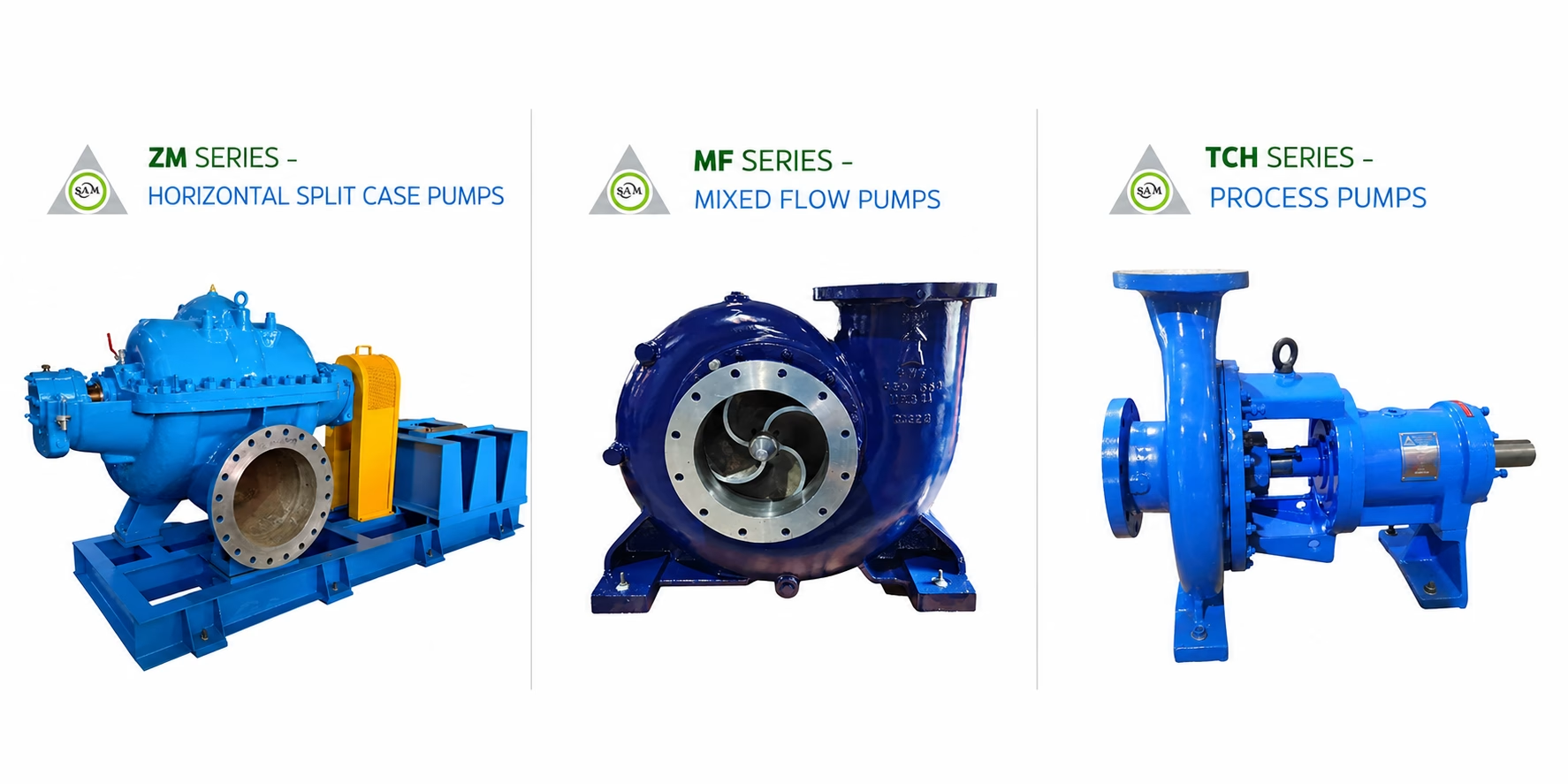
Whichever range suits your duty, the engineering team can review your flow range, suction layout and speed options before you order. More guidance is available in the pump engineering blog, the wider industrial pump range and the maintenance tips and operation tips pages.
Frequently Asked Questions
What is internal flow instability in a centrifugal pump?
It is the breakdown of smooth flow inside the pump, through backflow, flow separation and pressure pulsation, usually when the pump runs far from its best efficiency point.
What causes internal recirculation in centrifugal pumps?
Low flow forces the liquid to meet the impeller vanes at the wrong angle. Part of the stream reverses at the impeller eye (suction recirculation) or at the vane tips (discharge recirculation).
What is the difference between suction and discharge recirculation?
Suction recirculation starts at the impeller eye, while discharge recirculation starts at the vane tips. Both appear at low flow but cause damage in different places and need different checks.
How do I know if my pump has internal flow instability?
Typical signs are part-load noise, higher vibration, strong vane-pass peaks, pitted vane inlets and bearing or seal wear that does not match the pump’s service age.
Is flow recirculation the same as cavitation?
No. Cavitation comes from low pressure and vapour bubbles, while recirculation comes from flow angles and geometry. They can occur together and leave similar-looking damage.
What is vane-pass frequency and why does it matter?
It is the number of vanes multiplied by running speed in revolutions per second. A strong peak at that frequency points to pressure pulsation at the impeller outlet or cutwater.
Can running far from BEP damage bearings?
Yes. Off-BEP operation raises radial loads and shaft deflection, which shortens bearing and seal life even if the pump still delivers flow.
How can I reduce pressure fluctuations in a pump?
Operate nearer BEP, use speed control, correct the suction layout, check cutwater gap and impeller trim, and add minimum-flow protection where turndown is unavoidable.
Are mixed flow pumps more sensitive to low flow?
Generally yes. Higher specific-speed hydraulics tend to have steeper power curves and part-load disturbance, so the safe operating range should be defined at selection.
Which SAM Turbo pumps suit stable high-flow duty?
SAM Turbo’s Horizontal Split Case Pumps (ZM/AD) and Mixed Flow Pumps (MF) cover large-flow water and process duties, and its engineers review the operating range and suction layout before selection.
Conclusion
Centrifugal Pump Internal Flow Instability is not a random defect; it is the predictable result of asking a fixed hydraulic design to work outside the range it was built for, or feeding it a disturbed inflow. Suction and discharge recirculation, flow separation and pressure pulsation all grow as the duty moves away from BEP, and their costs appear as noise, vibration, bearing loads, seal failures and wasted energy. Plants that match the pump to the real duty range, protect minimum flow, tidy the suction layout and track vibration early usually avoid the worst of it. SAM Turbo’s engineers work through exactly this review for Horizontal Split Case Pumps (ZM/AD), Mixed Flow Pumps (MF) and Process Pumps (TCH+N), backed by in-house manufacturing, machining and performance testing. If a pump in your plant is noisy or vibrating away from its best point, they can help find the cause.
Pump vibrating or noisy away from its best point?
SAM Turbo’s engineering team can review your duty range, suction layout and operating data and recommend the right pump or fix.


